Flex Circuit Boards Tested For Reliability
In the electronics industry, reliability is an important factor in a product’s success. For flex circuit boards, this can mean ensuring the board’s functionality and adherence to specifications and standards. This is why it’s critical to have thorough testing processes in place for flex PCB prototyping and production.
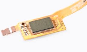
flex circuit board are used in many different electronic devices and industrial equipment, including calculators, cell phones, printers and LCD televisions. They are also found in medical devices such as heart monitors, pacemakers and hearing aids. Moreover, they are increasingly being used in military and aerospace applications. While a flex circuit board can be constructed in a variety of ways, the most common design is a single-sided flex PCB. These consist of a copper layer on one side and a protective solder mask on the other. The copper layer carries electrical conductors, while the solder mask protects them from corrosion and short circuiting.
A key element in a flex circuit’s performance is the amount of strain it can endure during bending. This is why it’s important to identify the minimum bend radius required for a flex PCB during the design phase. This can help prevent breakage and other defects during manufacturing. Ideally, the minimum bend radius should be larger than the maximum amount of flexing the circuit can experience.
How Are Flex Circuit Boards Tested For Reliability?
The most reliable flex circuits are made using high-quality materials that can withstand the test of time. These include conductors, which allow current to flow through the circuit; insulators, which separate and protect the conductors from each other; and substrates, which provide support and structure to the flex PCB. In addition, flex circuits should use a pressure sensitive adhesive (PSA) to hold components in place.
Before manufacturing, a flex circuit should be visually inspected to detect any visible defects. This can be done with a high-resolution camera or other inspection tools. The inspector should look for misalignment, welding defects, scratches or delamination. In addition, he or she should check the thickness and dimensions of the circuit to ensure they are within the specified tolerances.
A flex circuit should also be tested for its ability to resist corrosion, vibration, mechanical stress and other environmental factors. These tests can be performed using a variety of techniques, including accelerated life testing. These tests simulate the aging process of the circuit and determine its lifespan. In some cases, these tests may involve exposing the circuit to temperature cycling, humidity testing or chemical exposure.
X-ray inspection is another method that can be used to test the integrity of a flex circuit. This non-destructive test is able to detect cracks or voids in the PCB that would otherwise be difficult to see during a visual inspection. This test is especially useful for evaluating the quality of solder joints and ensuring that all component leads are properly attached to their respective pins.
When choosing a turnkey PCB manufacturer for flex circuits, it is important to understand the different types of testing available. For example, it’s essential to know if your manufacturer uses panel plating or pad-only-plating (button plating). Panel plating involves depositing copper on the entire surface of the circuit, while button plating deposits copper only on the pads/vias. Button plating offers superior results, as it allows manufacturers to control the copper thickness and width of the conductors. This can result in a better etch yield and reduce the size of the drill holes.