Prevent Signal Interference in Flexible PCBs
A flexible PCB can be subject to a lot of stress when it comes to the mechanical bending and folding it undergoes. This can lead to traces breaking, which is why careful design is necessary to prevent this from happening. Some of the factors that can lead to trace fractures include over-current, the use of heavy or rigid components near areas that require flexibility, and the lack of a minimum bend radius. Having a good understanding of the impact that these factors can have on your PCB’s ability to withstand bending will help you make better design choices that can protect your circuit board from failure in harsh environments.
The substrate material used in your PCB can have a huge effect on signal integrity. Different materials have varying dielectric constants and loss tangents, which can affect signal propagation and attenuation. Choosing a material that has a low dielectric constant will allow signals to move more quickly, reducing data corruption and improving the performance of your flexible pcb.
Using proper grounding techniques will also help you avoid signal interference. In addition, it is important to make sure that your traces are adequately spaced apart. The shortest traces should be the clock signal lines, followed by sensitive signals and then high-speed signal lines. This will reduce the amount of crosstalk between traces, which can cause EMI problems in your flex circuit board.
How to Prevent Signal Interference in Flexible PCBs?
Another way to prevent EMI is by using decoupling capacitors and shielding cables. These will absorb unwanted electromagnetic energy and prevent it from interfering with your signals. You can also minimize EMI by ensuring that your traces have the correct impedance matching and that they are routed as differential pairs.
Keeping your flexible PCB at the ideal temperature will also help with EMI and EMC performance. This is because heat can increase the resistance of copper and lead to a reduction in conductor efficiency. In order to keep your PCB at the right temperature, you should choose a thermal management solution that offers the best combination of durability and low cost.
To avoid EMI issues, you should select a layer stack that includes a ground plane and a power plane in the bottom of your PCB. This will prevent EMI from entering the circuit board through copper wires. In addition, you should choose a material that has a good etch and solderability for your PCB’s core. FR4 is a popular choice for this, as it is highly conductive and durable. If you want to further improve the EMI performance of your flex PCB, you can add stiffeners, which are small pieces of rigid material that are placed in selected areas to provide extra support and stability. They can also be made of metal, such as stainless steel or aluminum. By utilizing these tips, you can ensure that your flexible PCB meets the EMI and EMC standards required by your industry. This will ensure that it functions properly and does not interfere with other devices or equipment.
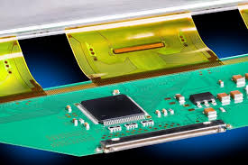
Connectors play a vital role in signal transmission between flexible PCBs and other components or systems. Flexible connectors, such as ZIF (Zero Insertion Force) connectors or FPC (Flexible Printed Circuit) connectors, provide reliable electrical connections while allowing for flexing and movement. Proper connector design and placement are critical for maintaining signal integrity and minimizing mechanical stress on the flexible PCB.